
3DPrinting Final Exam - Lecture Slides
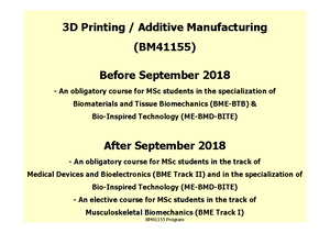
3D Printing (BM41155)
Technische Universiteit Delft

Gerelateerde documenten
- Flashcards m[5340]
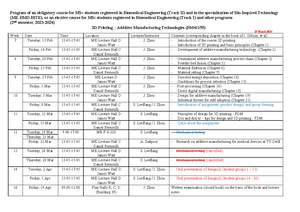
- BM41155 Program 2016-2017 [Compatibility Mode]
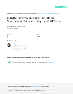
- Experimental Characterization of the Mechanical Properties of 3D-Printed ABS and Polycarbonate Parts 1
- Design of General Lattice Structure for Lightweight and Compliance Applications by David Rosen 1
- User’s guide FDM for End-Use Parts Tips and Techniques for Optimization by Stratasys 2
- User’s guide Design for Additive Manufacturability FDM Basics by Stratesys 1
Preview tekst
mAcronyms
3DP 3D Printing
AM Additive Manufacturing
AMF Additive Manufacturing File format (improved file format)
CAD Computer-Aided Design
CNC Computer Numerically Controlled machining
CW Continuous Wave (laser type used in PBF)
DED Directed Energy Deposition
EBM Electron Beam Melting
FDM Fused Deposition Modeling
LOM Laminated Object Manufacturing
LPS Liquid-Phase Sintering (PBF mechanism, partial melting)
LS Laser Sintering
mLS metal Laser Sintering
PBF Powder Bed Fusion
PCL polycaprolactane (material)
PLA polyactide (material)
pLS polymer Laser Sintering
SDM Shaped Deposition Manufacturing
SLS Selective Laser Sintering (see also: LS)
STL StereoLithography (file format)
Grey = probably not on the exam Chapter 1
Find three other denitions for rapid prototyping other than that of additive manufacturing as covered by this book.
From the web, nd different examples of applications of AM that illustrate their use for “Form,” “Fit,” and “Function.”
What functions can be carried out on point cloud data using Reverse Engineering software? How do these tools differ from conventional 3D CAD software?
- Combine point clouds from different scans
- Hole filling
- Smoothing
- Connect boundaries from adjacent layers of CT
- Individual patient data combined with engineering design completeness: RES: needs a lot of postprocessing: data may not be entirely complete/accurate, depends on scanning technology/ visibility of surfaces (ex. Crevices and internal features may have been obscured in the scan) CAD: this problem does not exist for CAD modeling speed: RES: fast modeling, little knowledge and skills on modeling required CAD: requires modeling skills
What is your favorite term (AM, Freeform Fabrication, RP, etc.) for describing this technology and why? Options: Additive manufacturing layer-based manufacturing additive fabrication (not subtractive) Automated fabrication (Autofab) (too general, including CNC) Freeform fabrication (FF) solid freeform fabrication (SFF) (complexity for free) Stereo-lithography (SL) 3D printing (3DP) (ink-jet printing-based) Rapid prototyping (RP) (getting closer to AM)
Create a web link list of videos showing operation of different AM technologies and representative process chains.
Make a list of different characteristics of AM technologies as a means to compare with CNC machining. Under what circumstances do AM have the advantage and under what would CNC?
CNC AM
Subtractive Additive
Hard Hard and soft
Provide three instances where a layer-based approach has been used in fabrication, other than AM.
- Relief maps
- Architects
- pyramids
Find ve countries where AM technology has been developed commercially and describe the machines.
Consider what a fabrication system in the home might look like, with the ability to manufacture many of the products around the house. How do you think this could be implemented?
Chapter 3
Investigate some of the web sites associated with different AM technologies. Find out information on how to handle the processes and resulting parts according to the eight stages mentioned in this chapter. What are four different tasks that you would need to carry out using a vat photopolymerization process that you wouldn’t have to do using a binder jetting technology and vice versa? Hold it in a vat, processed selectively by a laser, platform moving down,
Explain why surface modeling software is not ideal for describing models that are to be made using AM, even though the STL le format is itself a surface approximation. What kind of problems may occur when using surface modeling only?
- STL is essentially a surface description, consisting of a unordered collection of triangles and their corresponding surface normal vectors. Complex and discontinuous geometry may result in triangle vertices that do not align correctly and render unpredictable output.
- Most CAD are surface modelling + solid modelling
- Surface if they’re not fully enclosed results in unpredictable output
- AM fills gaps in unpredictable ways
What is the VRML le format like? How is it more suitable for specifying color models to be built using Color ZCorp machines than the STL standard? How does it compare with the AMF format?
- VRML painting options allow you to assign bitmap images to individual facets. In such a way, it is possible to take advantage of the color possibilities that the AM machine can give you. (VRML is actually meant for virtual reality, or interactive 3D environments for the internet, therefore includes more possibilities, including textures and bitmaps, material properties)
- STL les are an unordered collection of triangle vertices and surface normal vectors. As such, an STL le has no units, color, material, or other feature information. These limitations of an STL le have led to the recent adoption of a new “AMF” le format. This
format is now an international ASTM/ISO standard format which extends the STL format to include dimensions, color, material, and many other useful features. As of the writing of this book, several major CAD companies and AM hardware vendors had publically announced that they will be supporting AMF in their next generation software. Thus, although the term STL is used throughout the remainder of this textbook, the AMF le could be simply substituted wherever STL appears, as the AMF format has all of the benets of the STL le format with many fewer limitations.
What extra considerations might you need to give when producing medical models using AM instead of conventionally engineered products?
- Processing to extract relevant sections from imaging data (segmentation)
Consider the FigurePrints part shown in Fig. 3, which is made using a color binder jetting process. What nishing methods would you use for this application?
- polishing
- removal of support material
- infiltration (might not be necessary for this model, as infiltration is used to change the material properties, when mechanical properties are of importance)
Chapter 5 Video showing how PBF works youtube/watch?v=te9OaSZ0kf
Find a reference which describes an application of the Arrhenius equation to solid state sintering. If an acceptable level of sintering is achieved within time T1 at a temperature of 750 K, what temperature would be required to achieve the same level of sintering in half the time?
Estimate the energy driving force difference between two different powder beds made up of spherical particles with the same total mass, where the difference in surface area to volume ratio difference between one powder bed and the other is a factor of 2.
- the binder % content required for effective fusion of coated particles is usually less than the binder content required for effective fusion of randomly mixed particles
- If a structural particle is coated with the binder material then the impinging energy must rst pass through the coating before affecting the structural material. As melting of the binder and not the structural material is the objective of LPS, this helps ensure that the proper constituent melts.
- Polycaprolactone (PCL) is a biodegradable polyester with a low melting point
- Hydroxyapatite is a ceramic
Using standard kitchen ingredients, explore the powder characteristics described in Sect. 5.5 and powder handling options described in Sect. 5.5. Using at least three different ingredients, describe whether or not the issues described are reproducible in your experiments.
Using an internet search, nd a set of recommended processing parameters for nylon polyamide using laser sintering. Based upon (5), are these parameters limited by machine laser power, scan spacing, or scan speed? Why? What machine characteristics could be changed to increase the build rate for this material and machine combination?
Using Fig. 5 and the explanatory text, estimate the minimum laser dwell time (how long a spot is under the laser as it passes) needed to maintain a type B scan track at 100 W.
- Minimum scan speed is 2mm/s, maximum is 10mm/s
- 1 beam divided by 2mm/s = 0 seconds laser dwell time (Max)
- 1 beam divided by 10mm/s = 0 seconds laser dwell time (Min)
Chapter 6
Derive an expression for QT so that we can determine the ow through a circular extrusion nozzle.
The expression for total ow does not include a gravity coefcient. Derive an expression for QT that includes gravity, assuming there is a constant amount of material in the melt chamber and the nozzle is pointing vertically downwards.
The forces generated by the pinch rollers shown in Fig. 6 to the elastic modulus.
The expressions derived for solidication and bonding assume that a thermal process is being used. What do you think the terms will look like if a curing or drying process were used?
Why is extrusion-based AM more suitable for medical scaffold architectures, compared with SLS-fabricated scaffolds made from a similar material?
- Scaffolds are generally built up so that roads are separated by a set distance so that the scaffold can have a specic macro porosity. In fact, the aim is to produce scaffolds that are as strong as possible but with as much porosity as possible. The greater the porosity, the more space there is for cells to grow. Scaffolds with greater than 66 % porosity are common. Sometimes, therefore, it may be better to have a thicker nozzle to build stronger scaffold struts. The spacing between these struts can be used to determine the scaffold porosity.
- This technique has full control over porosity, pore size, pore shape and permeability to the scaffold structure. The implants produced by the extrusion based AM process are low cost.
In what ways is extrusion-based AM similar to CNC pocket milling and in what ways is it different? Firstly, a CAD or CAM 3D model is needed from which the design can be implemented. Extrusion based AM can be used for very complex designs and CNC pocket milling can be used for a wider range of materials and produces stronger products. Extrusion based AM is additive manufacturing while cnc pocket milling is subtractive manufacturing? CNC is slow, AM is quick
Chapter 7
List ve types of material that can be directly printed.
- Maximum printable viscosity = 20-40cP
- Need a low enough melting temp that the nozzle is not damaged by the heat
- Alumina particles in a wax carrier (not “directly printed”)
Develop a build time model for a printing machine. Assume that the part platform is to be lled with parts and the platform is L mm long and W mm wide. The print head width is H mm. Assume that a layer requires three passes of the print head, the print head can print in both directions of travel (+X andY), and the layer thickness is T mm. Figure 7 shows a schematic for the problem. Assume that a delay of D seconds is required for cleaning the print heads every K layers. The height of the parts to be printed is P mm. (a) Develop a build time model using the variables listed in the problem statement. Compute the build time for a layer of parts given the variable values in the following table.
Modify the build time model from Problem 4 for the 3DP process. Assume that the powder bed recoating time is 10 s. Compute build times for a layer of parts using the values in Problem 4, assuming that layer thicknesses are 0 mm.
The integral in (7) can be evaluated analytically for simple nozzle shapes. Assume that the nozzle is conical with the entrance diameter of de and the exit diameter dx. (a) evaluate the integral analytically. Use your integrated expression to compute pressure drop through the nozzle, instead of (7), for the following variable values:
Using the integral from Problem 6, develop a computer program to compute pressure drop through the nozzle for various nozzle sizes and uid properties. Compute and plot the pressure drop for the printing conditions of Fig. 7, but using nozzles of the following dimensions: (a) l¼0 mm, de¼0 mm, dx¼0 mm (b) l¼0 mm, de¼0 mm, dx¼0 mm (c) l¼0 mm, de¼0 mm, dx¼0 mm (d) l¼5 mm, de¼0 mm, dx¼0 mm
Chapter 10 Video showing how DED works: youtube/watch?v=Pjqysyy1ySs
- Discuss three characteristics where DED is similar to extrusion-based processes and three
characteristics where DED is different than extrusion-based processes.
Similar:
- Both involve melting material as it is deposited
- Can both use wire/filament
- Both use a deposition head
- Both can use multiple nozzles to deposit different materials
Different: - DED mostly for metals, extrusion for both (common for polymers) - DED can use powder or wire feedstock, extrusion doesn’t use powder - DED uses lasers/electron beam, extrusion doesn’t - DED can deposit vertically or non vertically, extrusion needs to be down - DED has very high cooling rates, extrusion slower - DED can dynamically change travel speed based on feedback, I don’t think extrusion can?
Read reference [4] related to thin-wall structures made using DED. What are the main differences between modeling thin wall and bulky structures? What ramications does this have for processing?
Why is solidication rate considered the key characteristic to control in DED processing?
- Because it determines the microstructure
From the literature, determine how solidication rate is monitored. From this information, describe an effective, simple closed-loop control methodology for solidication rate.
What are the key material property considerations when selecting a secondary support material for material jetting and material extrusion? Would these considerations change when considering supporting metals deposited using a directed energy deposition process?
What are the primary benets and drawbacks when offsetting triangle surfaces versus triangle vertices? (Note: You will need to nd this information by nding and reading a relevant paper, as the details are not in this chapter.) Which approach would be better for freeform surfaces, such as the hood of a car or the prole of a face?
Assuming that the total shrinkage in an AM process is represented by Fig. 14, what shrinkage value and what surface offset value would you choose for pre-processing a model for each of the Factors A–F?
Why is contour milling benecial for parts if adaptive raster milling ensures that all cusp heights are within acceptable values?
In AM processes often a larger shrinkage value is found in the X–Y plane than in the Z direction before post-processing. Why might this be the case?
Chapter 16
Estimate the build time and cost for a platform of 100 aligner mold parts in an iPro 8000 SLA Center (see Chap. 4). Assume that the bounding box for each part is 11128 cm and the mold volume is 75,000 mm3. Assume a scanning speed of 5,000 mm/s and a jump speed of 20, mm/s. All remaining quantities are given in Sect. 16. What is the estimated cost per mold (two parts)?
A vat of hearing aid shells is to be built in an SLS Pro 140 machine (build platform size: 550550460 mm). How many hearing aid shells can t in this build platform? Determine the estimated build time and cost for this build platform full of shells. Assume laser scan and jump speed of 5,000 mm/s and 20,000 mm/s, respectively. Assume the laser spot size is 0 mm, layer thicknesses are 0 mm, and only 1 scanning pass per layer is needed (nst¼1). Assume 4 mm gaps in X, Y, and Z directions. Recall that no support structures are needed. Assume that the SLS machine needs 2 h to warm up and 2 h to cool down after the build. Assume that Tpredelay is 15 s and Tpostdelay is 2 s.
Develop a build time model for a jetting machine, such as the Eden models from Stratasys or the ProJets from 3D Systems. Note that this is a line-type process, in contrast to the point-wise vector scanning process used in VP or PBF. Consider that the jetting head can print material during each traversal of the build area and nst may be 2 or 3 (e., two or three passes of the head are required to fully cover the total build area). Assume that Tpredelay and Tpostdelay are 2 s.
Estimate the build time and cost for a platform of hearing aid shells in an Eden 500 V machine (see Chap. 7). What is the estimated cost per shell? You will need to visit the Stratasys web site and possibly contact Stratasys personnel in order to acquire all necessary information for computing times and costs.
Develop a build time model for an ME machine from Stratasys, such as the Fortus 900mc. Note that this is a point-wise vector process without overlapping scans. Scan speeds can be up to 1,000 mm/s. Assume that a warm-up time of 0 h is needed to heat the build chamber. Assume that Tpredelay and Tpostdelay are 1 s.
Estimate the build time and cost for a platform of hearing aid shells in a Fortus 900mc material extrusion machine. What is the estimated cost per shell? You will need to visit the Stratasys web site and possibly contact Stratasys personnel in order to acquire all necessary information for computing times and costs.
Modify the model for purchase cost to incorporate net present value considerations. Rework the hearing aid shell example in Sect. 16.6 to use net present value. What is the estimated cost of a shell?
Bentley Motors has a production volume of 10,000 cars per year, over its four main models. Production volume per model per year ranges from about 200 to 4,500. Since each car may sell for $120,000 to over $500,000, each car is highly customized. Write a one-page essay on the DDM implications of such a business. The engines for these cars are shared with another car manufacturer; as such, do not focus your essay on the engines. Rather, focus on the chassis, interiors, and other parts of the car that customers will see and interact with.
Chapter 17
1.–4. Describe in your own words the four AM unique design capabilities described in this chapter and give one example of a product that could be improved by the proper application of each design capability. The example products cannot be ones that were mentioned in this book. 1. Shape Complexity 2. Hierarchical Complexity 3. Functional Complexity
- Printing a seatbelt buckle for airplanes in one piece, no assembly required
- Material Complexity
- Turbine blade for a jet engine where outside is stiff and resistant to high temps, and root is ductile and has a high fatigue life
- What are three ways that current designers are trained that are at odds with the concept of DFAM?
3DPrinting Final Exam - Lecture Slides
Vak: 3D Printing (BM41155)
Universiteit: Technische Universiteit Delft

- Ontdek meer van:
Andere studenten bekeken ook
Gerelateerde documenten
- Flashcards m[5340]
- BM41155 Program 2016-2017 [Compatibility Mode]
- Experimental Characterization of the Mechanical Properties of 3D-Printed ABS and Polycarbonate Parts 1
- Design of General Lattice Structure for Lightweight and Compliance Applications by David Rosen 1
- User’s guide FDM for End-Use Parts Tips and Techniques for Optimization by Stratasys 2
- User’s guide Design for Additive Manufacturability FDM Basics by Stratesys 1